Chapter 3 — Shape Tools
The Shape tab has more than just the modelling-mode picker. This chapter covers the auxiliary tools that apply across every mode: wall and floor controls, the dimensions overlay, the pottery wheel (experimental), and the build-plate / printer matching.
Wall & Floor
Every printable vase is hollow. The Wall & Floor panel sits below the modelling-mode panels and controls the inner cavity:
- Closed Solid (default ON) — when on, the model is a hollow vessel with the inner cavity carved out. When off, the model is a fully filled solid (rare; useful for paperweights or architectural samples).
- Wall Thickness (mm) — gap between the outer and inner surface. Typical clay-print walls are 2.5–4 mm.
- Bottom Thickness (mm) — thickness of the solid base, measured upward from y=0. The cavity only opens above this height.
- Open Top (default ON) — leaves the rim open. Uncheck for a closed dome (perfect for sealed bottles or sealed-base sculpture).
These four settings drive every mesh path: revolution, single-object loft, and the SDF-based multi-object loft all honour them identically.
Panel resets
Three panels carry a small ⟲ Reset button in their header, on the right-hand side of the title row:
- Object Settings — snaps Height, Diameter, Scale X/Y/Z, Scale Uniform, Profile Shape, and Chamfer Radius back to application defaults. Your name, modelling mode, profile points, and lofting layers are left intact.
- Texture Dimension — replaces the entire texture configuration with a fresh one (clears any 1D / 2D / Graph customisation).
- Surface Effect — wipes any active Voronoi / Strip / Cut-Through effect back to "None".
Each reset opens a confirmation dialog — "Reset [panel name]? This can't be undone." — before applying. Cancelling the dialog leaves everything as-is.
Base Settings
The Base Settings panel (below Wall & Floor) tunes the printed foot/skirt — the few millimeters of clay laid down at the very base of the print to lock the part to the build plate:
- Base Offset (mm) — radial distance of the skirt from the model wall.
- Base Height (mm) — physical height of each base layer.
- Base Layers (1–4) — how many extra base layers to stack.
- Base Ratio (%) — extrusion-volume multiplier for the base layers (some clay needs 150–200% on the first layers to avoid gaps).
These are baked into the G-code on export — they don't change the viewport mesh.
Dimensions overlay
Toggle the ↕ Dimensions button in the top-right viewport overlay (or press its hotkey) to show a comprehensive measurements panel.
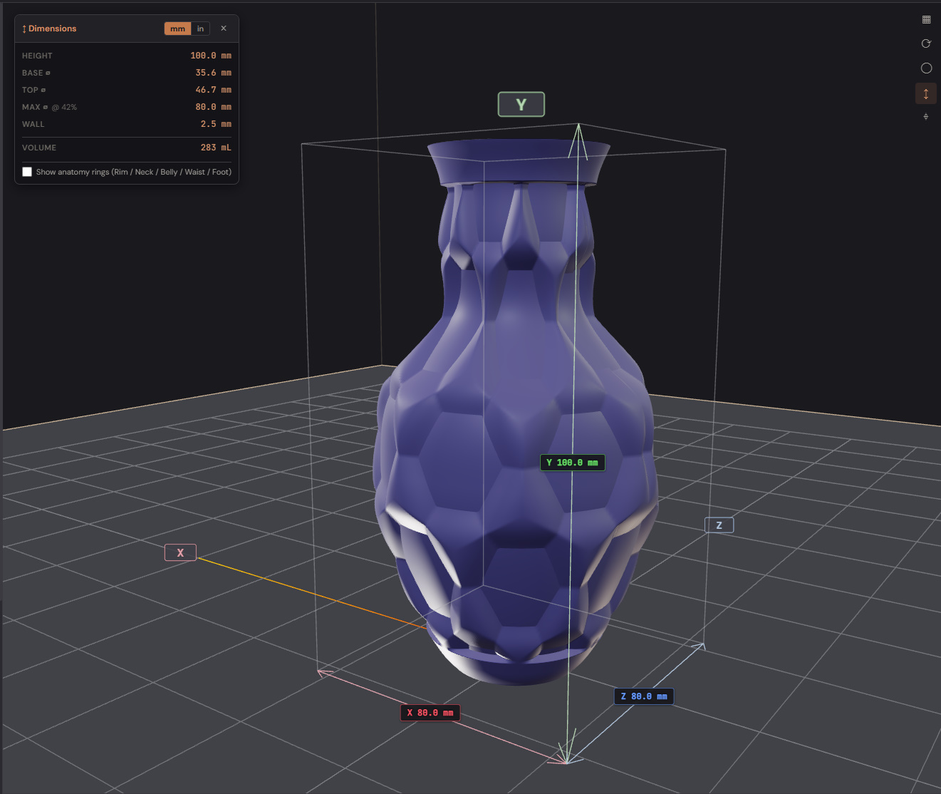
What you get:
- Floating corner panel — Height, Base ⌀, Top ⌀, Max ⌀, Wall, Volume.
Toggle between mm and inches with the
mm ↔ inswitch in the panel. - Bounding cage — 12 thin grey edges around the model. Three of them are colour-coded red (X), green (Y), blue (Z) with width / height / depth labels.
- Anatomy rings — five horizontal hoops at named landmarks:
- A — Rim (very top)
- B — Neck (auto-detected upper local minimum)
- C — Belly (the widest point)
- D — Waist (auto-detected lower local minimum, if present)
- E — Foot (bottom)
- Each ring shows its letter + diameter label tracking with the camera.
The rings adapt to your profile — if there's no clear neck, the system falls back to even spacing. Useful when discussing a design ("can we narrow B by 4 mm?") because the language is unambiguous.
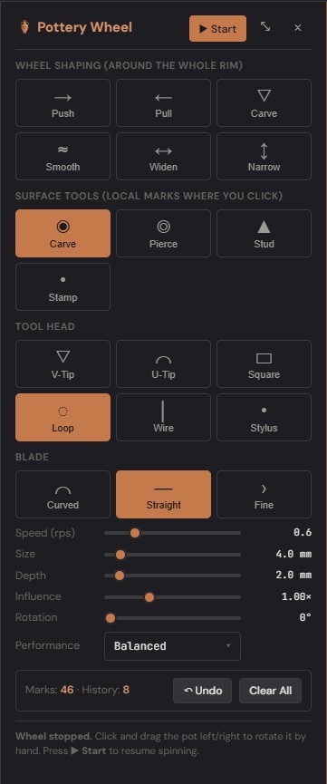
Pottery Wheel (experimental)
Settings → Experimental → tick Pottery Wheel to expose the Tools menu's 🏺 entry. When enabled, the model is mounted on a virtual wheel and you sculpt by clicking on it. Pottery mode is available only when the model is in Revolution mode — opening it from any other mode is disabled to protect lofting / multi-object work from being wiped.
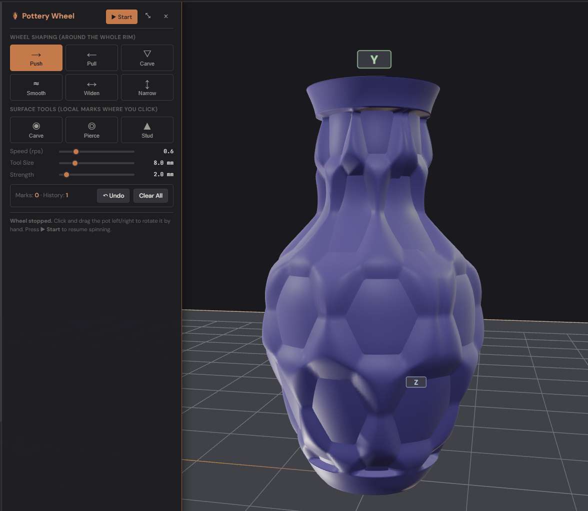
Entering and leaving the wheel
The wheel starts stopped when you enter pottery mode so you can place the first stamp / pierce before the surface scrolls under your cursor. Press ▶ Start in the pottery panel to spin at the chosen Speed; press ⏸ Stop to pause. With the wheel stopped you can drag horizontally on the model to manually rotate it (like braking a real wheel and turning the pot by hand). Right-mouse drag still orbits the camera in every state.
Pottery mode is mutually exclusive with the Profile pop-out, the Pattern Graph editor, and the Settings dock — opening any one of those closes the others (Settings remembers what was open and restores it on close).
Wheel-shaping tools (wheel running)
These tools modify the silhouette underneath the surface. Wheel must be spinning.
- Push / Pull — radial deformation. Push squeezes the wall inward, Pull bulges it outward.
- Carve / Smooth — depth-only changes. Carve digs a local hollow, Smooth flattens nearby variation.
- Widen / Narrow — height-band scaling. Widen splays a band outward, Narrow pinches it.
Surface tools (wheel stopped)
These place per-click marks at a fixed position on the wall. The wheel must be stopped — the wheel-running variant of stamping is Roller (see below).
- Local Carve — single inward dent at the click position. Tool Head (V-Tip / U-Tip / Square / etc.) drives the cut cross-section.
- Pierce — punches a hole all the way through the wall. Punch patterns: Round, Oval, Diamond, Square, Triangle.
- Stud — raised dome on the outer surface. Same Tool Head set as Local Carve.
- Stamp — single-shot impression of a curated pattern (see below).
Stamp tool
Stamp prints a single full-size impression of the picked pattern wherever you click. Patterns ship as built-in polygons (Circle, Star, Heart, Dots, Diamonds, Zig-Zag, Triangle, Square, Hexagon) and can be extended via the Pattern Library (see below).
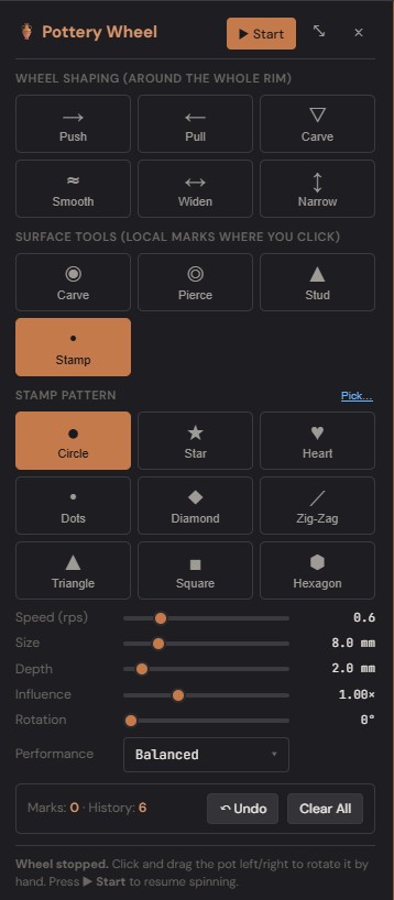
Pattern-specific controls:
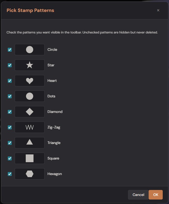
- Pick… link next to the Stamp Pattern label opens a checklist of every available pattern with a preview thumbnail. Uncheck the ones you don't use to keep the toolbar uncluttered. Selection is saved globally in app settings.
- Outline Snap slider (Star/Heart/Diamond/Triangle/Square/Hexagon only) — controls how aggressively the cut boundary is pulled onto the polygon outline. 1.0 = sharpest 2D shape; lower values give a softer cell-grid look and reduce the small feathering that radiates outward from the cut into the wall. Default 1.0 with internal smoothstep falloff keeps the polygon edge clean without visible bristles.
Roller tool
Roller behaves like a series of stamps printed continuously as the pot spins under the cursor. Same pattern picker as Stamp, with three extra controls in the panel:
- Spacing slider — rough density of stamps per revolution. 0.3× = tightly packed (stamps may overlap); 1× = nominal; 3× = wide gaps.
- Auto Space checkbox — when on, the spray pump fires by position (not by time), and rounds the count of stamps per revolution to a whole number. The Spacing slider still controls rough density; Auto Space snaps the result to a count that divides 2π evenly so the pattern wraps around the pot with no seam mismatch at the start/end of a rotation. Different heights on a vase silhouette have different circumferences — Auto Space recomputes the count per sample so each height gets its own evenly-divided pattern.
- Per-sample interpolation (Carve's behaviour, which fills gaps between samples for a continuous trail) is intentionally skipped for Roller — each spray sample produces one discrete stamp.
Pattern Library
Tools → 📐 Pattern Library… opens a modal that manages user-imported SVG patterns. Imported patterns appear alongside the built-in set in the Stamp / Roller pickers.

- Import SVG… — file picker for
.svgfiles. The first polygon-shaped element in the SVG is parsed (<polygon>,<polyline>, or<path>with M/L/Z commands) and normalised to a unit box. Curves in<path>data are flattened to straight segments between control endpoints — convert curves to lines in your SVG editor for the cleanest result. - Where the files live — under
LibraryFolderPath/patterns/(the same folder root as your project library). Back them up, share between machines, or hand-edit the .svg files freely. - Delete per row removes the file and the cached polygon.
Other pottery controls
- Size, Depth, Influence — common to every tool. Size is the footprint radius (mm); Depth is per-stroke wall displacement (mm); Influence is a "how firm" multiplier on each spray sample.
- Rotation — surface tools only. Rotates non-circular footprints around the surface normal.
- Performance dropdown — Quality / Balanced / Performance. Drops shadow + pixel-ratio while the wheel is active so a spinning Retina pot stays interactive. Restored to full quality on exit.
- Clear All — resets every wheel-tool mutation and every surface mark back to the silhouette you had when entering pottery mode.
Undo and export
Undo per-stroke is captured automatically. Press Ctrl+Z (or use the toolbar undo) to roll back the most recent gesture. The pottery panel shows the running mark count and undo-stack depth so you can see when the session is getting heavy.
Pottery marks (Carve / Stud / Stamp / Roller) and Pierce holes both
flow into STL and OBJ exports — the export pipeline runs the same
ApplyPotteryVertexMarks bake the viewport uses, so what's on screen
is what lands in the exported mesh.
Build plate & printer matching
The build plate is the translucent ground plane in the viewport — it's sized to the printer you've selected so you can sanity-check that the model fits before exporting.
Set the printer in the Settings → Defaults → Printer dropdown (or load it on a per-project basis). Built-in presets cover:
- Bambu Lab — X1, X1 Carbon, P1S, P1P, A1, A1 mini, H2D, H2.
- Prusa — MK4, MK4S, XL, MINI+, MK3S+.
- Elegoo — Neptune 4, Neptune 4 Pro, Centauri Carbon.
- Eazao (clay) — Sevenlite, Mega, Zero, Zero V2, Octopus, Pro, Q1, M500, M600, M700.
- WASP (clay) — DeltaWASP 2040, 4070, 60100 LDM.
- 3D Potter (clay) — Micro 10, Scara V4, Skywalker XL.
- Stoneflower (clay) — 3D Pro, Mini.
- Cerambot (clay) — Eazao, Power.
- Custom — set your own width / depth / diameter / height.
Round build plates (delta printers, most clay machines) display as a disc; rectangular plates display as a rectangle. The dimensions are real millimetres, so the model's reported height / diameter directly compare.
If your model exceeds the build volume in any axis, the export-quality mesh is still produced — but the Analysis tab flags an "exceeds plate" warning so you know.
Analysis tab
The Analysis sidebar tab runs a structural-stability check on the current model and reports a 0–100 stability score plus a list of per-region warnings. It's the "is this thing actually printable?" sanity check.
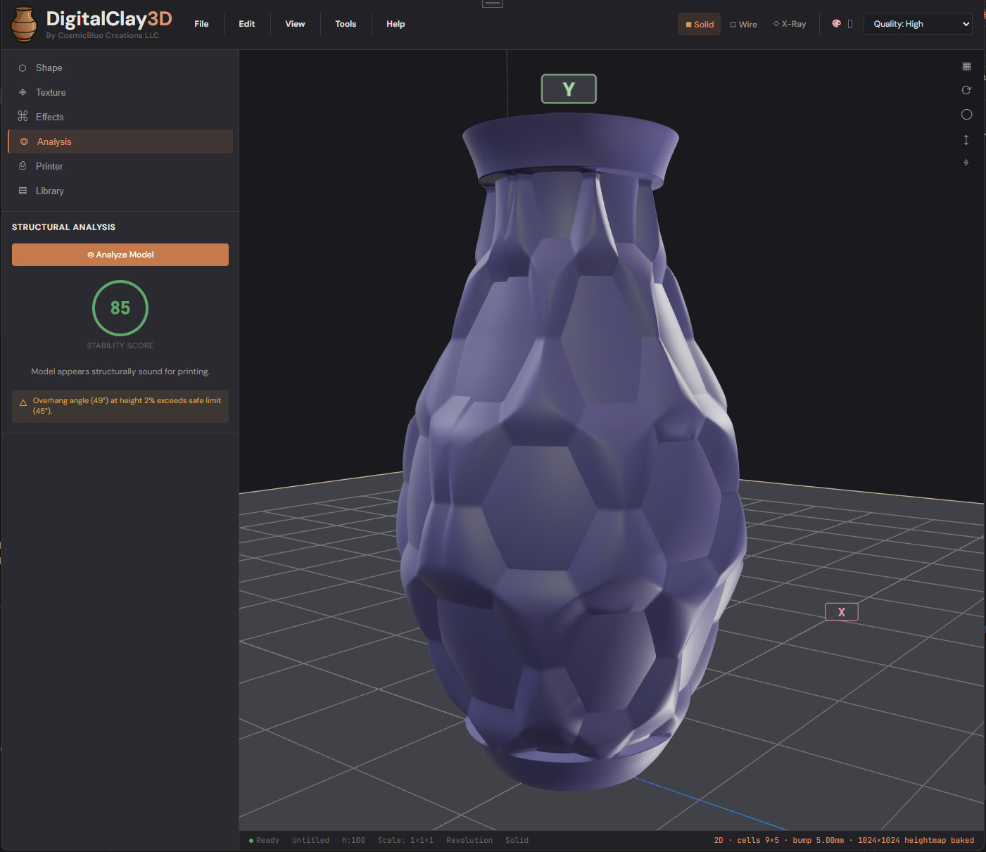
Click ⊙ Analyze Model to (re)run the check. The result panel shows:
- Stability Score — a coloured 0..100 ring. Green ≥ 70 is generally printable; amber 40–70 may print with care; red < 40 is likely to collapse during print.
- Verdict line — short summary ("Model appears structurally sound for printing" / "Model is top-heavy, expect collapse near layer X" / etc).
- Per-region warnings — each warning carries a height position, a severity (Info / Warning / Critical), and a short message. Common ones: "Overhang angle (49°) at height 2 % exceeds safe limit (45°)", "Wall thickness drops below 1.5× nozzle diameter at height 78 %", "Top-heavy — top 30 % wider than bottom 30 %".
Re-run after every significant edit. Analysis is cheap (a few hundred ms even on heavy models).
Printer tab (experimental)
Settings → Experimental → tick Printer Path Simulation to expose the Printer sidebar tab. It does two things: it shows the build plate match (manufacturer + model dropdowns, plate shape, dimensions, and a green "Model fits the build volume" / red "Exceeds plate" indicator), and it runs a layer-by-layer toolpath simulation with gravity-aware droop prediction so you can spot collapses before committing clay.
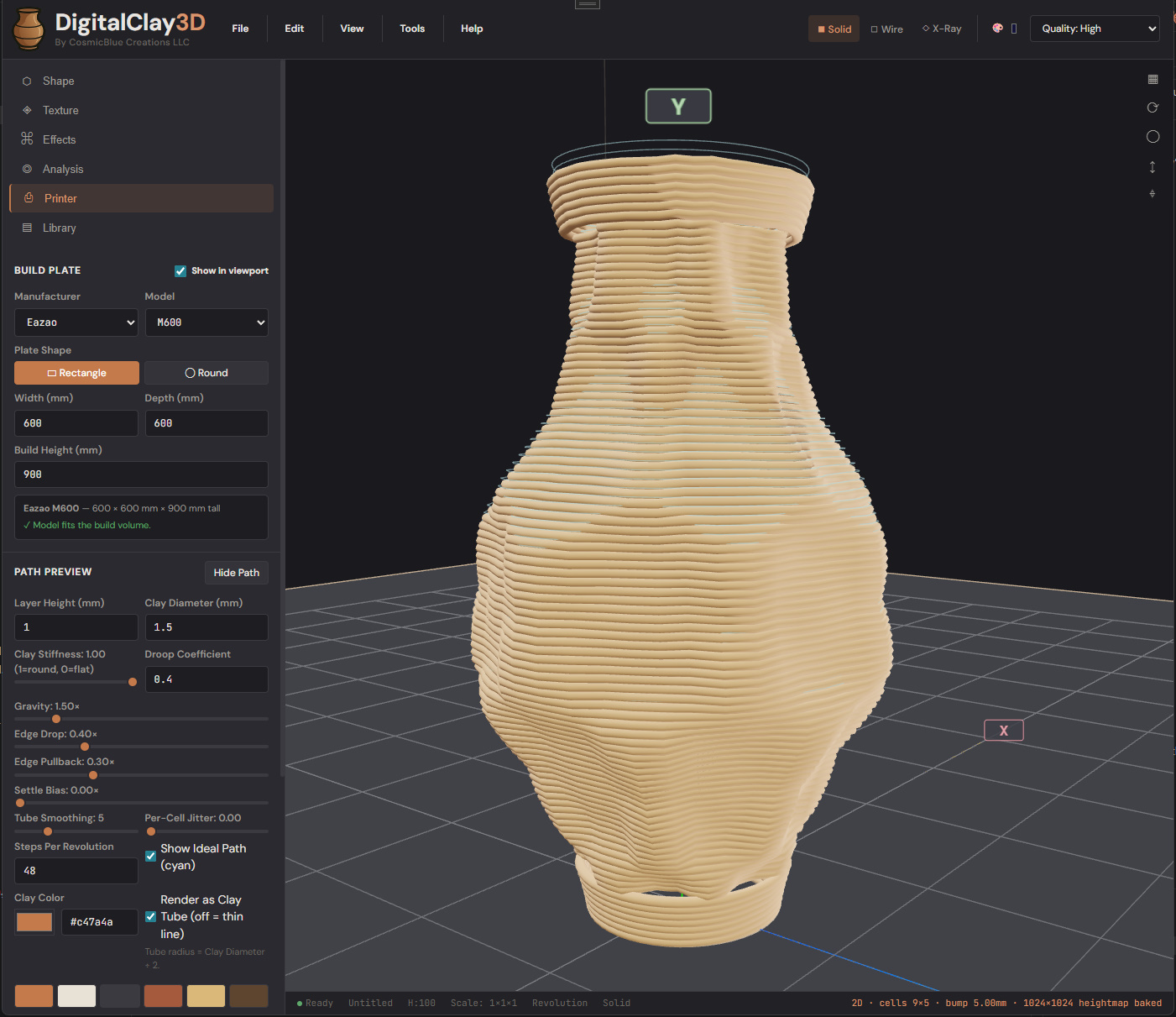
Build plate group:
- Manufacturer / Model dropdowns — pick from the built-in catalog (Bambu Lab, Prusa, Eazao, WASP, 3D Potter, Stoneflower, Cerambot, or Custom). The plate dimensions auto-fill; the green band confirms the fit.
- Plate Shape toggle — Rectangle / Round. Use Round for delta printers and most clay machines.
- Width / Depth / Build Height — editable when "Custom" is the selected model.
Path Preview group — the tunable parameters that drive the simulator:
- Layer Height (mm) / Clay Diameter (mm) — match your printer.
- Clay Stiffness (1 = round, 0 = flat) — wet clay slumps; dry clay holds shape. Slider drives how much each layer flattens under the next one's weight.
- Droop Coefficient / Gravity — gravity multipliers, larger = more sag.
- Edge Drop / Edge Pullback — how far overhanging beads sag and whether they retract toward the wall as they sag.
- Settle Bias — additional compaction on lower layers from the weight above.
- Tube Smoothing — how many neighbouring segments share the droop calculation (smooths the simulated tube).
- Per-Cell Jitter — adds organic per-bump variation so identical texture cells don't all melt the same way.
- Steps Per Revolution — path resolution.
- Show Ideal Path — overlay the zero-droop reference path in cyan alongside the simulated (sagged) path so you can see exactly where the model is misbehaving.
- Render as Clay Tube — full clay-coloured tube (default) vs a thin colour-coded line.
- Clay Color — picks the swatch shown for the rendered tube.
Hide Path removes the simulation overlay; Show redraws. Re-render after any model change to see the updated prediction.
The simulator runs on the threadpool so the UI stays responsive during long calculations. Heavy textures + Cut Through can take a few seconds.
What to read next
- Chapter 4 — Surface Decoration for the texture system.
- Chapter 9 — Settings for the full Settings dialog reference (defaults, rendering, license, experimental).